Environmental Engineering Reference
In-Depth Information
(a)
(b)
Pgr = 150 mW, v1rated = 4.2 m/s, cut-in = 2.0 m/s, cut-off = 5.0 m/s
Regions 1,2,3 for 100% case are: v1 = 2.0 to 3.6, 3.6 to 4.2, 4.2 to 5.0
For 100% case: Wr-rated = 324 rpm, v1rated = 4.2 m/s
cut-in: 2.0 m/s, 180 rpm, cut-off: 5.0 m/s, 324 rpm
400
160
350
140
120
300
100
250
80
60
200
40
150
20
0
100
1.5
2
2.5
3
3.5
4
4.5
5
1.5
2
2.5
3
3.5
4
4.5
5
Wind speed v1 (m/s)
Wind speed v1 (m/s)
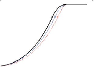
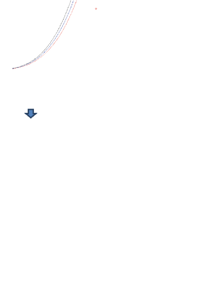
Fig. 14.26 Experimental characterization of a 6-blade rotor wind turbine for 100, 90 and 80 %
C
pmax
: a Power curves; b Rotor speed versus wind speed
Topology 1
Topology 2
Topology 3
Topology 4
Topology 5
Topology 6
Fig. 14.27 Wind farm topology configurations for different global power efficiency, with T1
,T2
,T3
,T4
Figure
14.27
and Tables
14.3
,
14.4
,
14.5
shows the configuration of the wind
farm for six different experiments. Each wind turbine has a 6-blade rotor, has no
active controllers, a constant pitch angle b = 0, a constant yaw angle a = 0, and a
constant demanded torque T
gd
. The geometric position of each wind turbine in the


