Environmental Engineering Reference
In-Depth Information
v
1
(
s
)
D
1
s
)
β
d
(
s
)
Ω
r
(
s
)
Ω
r_ref
+
+
P
(
s
)
G
(
s
)
+
-
H
(
s
)
T
gd
(
s
)
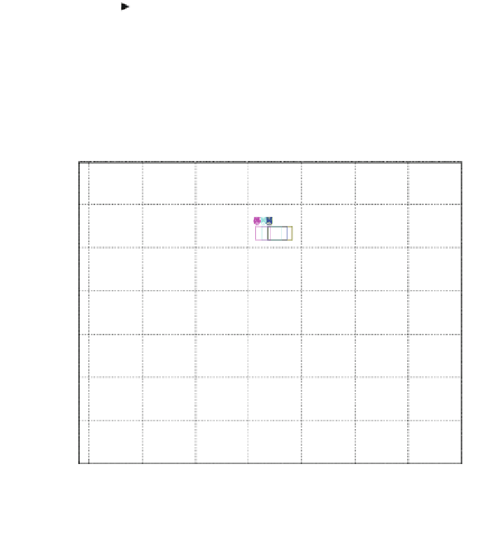
Fig. 14.16 Simplified block diagram for rotor speed control system [
2
]
Nichols plot
0
-20
0.5
0.3
0.1
0.05
0.01
0.001
0.005
0.7
-40
1
1.
1
1.3
1.5
2
-60
3
5
-80
7
-100
Nominal plant
10
-120
-140
-350
-300
-250
-200
-150
-100
-50
0
Open-loop phase (deg)
Fig. 14.17 QFT templates for X
rs
(s)/b
di
(s) and x = [0.001 0.005 0.01 0.05 0.1 0.3 0.5 0.7 1 1.1
1.3 1.5 2 3 5 7 10] rad/s
Specification 2 (Robust Output Disturbance Rejection).
X
r
ð
jx
Þ
d
ð
jx
Þ
1
1
þ
Pj
ðÞ
Gj
ðÞ
6jx
6 jx
þ
1
¼
;
for x
ð
14
:
41
Þ
¼
0
:
001
½
0
:
005
0
:
01
0
:
05
0
:
1
rad/s
The QFT bounds are calculated with the QFT Control Toolbox [
2
,
3
] and are
shown in Fig.
14.18
, with the worst case scenario (intersection of bounds) for the
stability and output disturbance rejection specifications and for X
rs
(s)/b
di
(s)—
Eq. (
14.39
)—at all the frequencies of interest.