Environmental Engineering Reference
In-Depth Information
v
1
(s)
m/s
Ω
r
1
(s)
rpm
1
/c
2
F
1
(s)
rad/sec
F
3
(s)
A
T
(s)
T
gd
(s)
Nm
T
g
(s)
Nm
Ω
r
3
(s)
rpm
Q
(s)
Eq . (3 7 )
G
t
(s)
1
/c
2
rad/sec
Generator
F
2
(s)
Actuator
β
m
(s)
deg
motor
output
Ω
r
(s)
rad/sec
β
d
(s)
rad at
actuator
β
di
(s)
deg at
actuator
input
(s)
deg at
nacelle
sensor
β
Ω
r
2
(s)
rpm
Ω
rs
(s)
rpm
rotor
sensor
A
β
(s)
Eq. (35)
P
1
(s)
Eq. (34)
error
rad/sec
G
p
(s)
c
1
r
tg
c
2
tower
gearbox
NXT motor
Rotor dynamics
−
Ω
r_ref
(s)
rad/sec
+
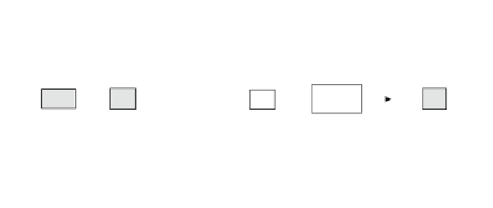
Fig. 14.14 WT control system block diagram
b(s)/b
di
(s) = A
b
(s)r
tg
are identified experimentally by applying step inputs to the
pitch motor of the wind turbines under different wind speeds. Figure
14.14
shows the
input/output signals.
For the estimation of the first transfer function the wind speed is set as a
periodic function v
1
= v
1m
+ v
1a
sin(2pft+ h) m/s, with v
1a
= 0.125 m/s,
f = 0.2 Hz, and h = 58, and under three scenarios of average wind speed:
v
1m
= 3.68, 4.22, and 4.75 m/s. During the experiments the generator torque T
gd
and the yaw angle a = 0 are maintained constant. Then the pitch angle at the
nacelle b is changed from 0 to 5 and the rotor speed X
rs
is measured. For the
second transfer function a second experiment studies the wind turbine with no
wind (v
1
= 0) and constant torque T
gd
, when the actuator input b
di
is changed from
0 to 700 and the actual pitch angle at the nacelle b is measured.
Using the signals obtained in these experiments and applying classical system
identification
techniques,
the
structure,
parameters,
and
uncertainty
of
both
transfer functions are found as shown in Eqs. (
14.34
) and (
14.35
).
X
rs
ð
s
Þ
b
ð
s
Þ
¼
P
1
ð
s
Þ¼
k
1
ð
14
:
34
Þ
2
þ
2 f
1
s
s
x
n1
x
n1
þ
1
b
ð
s
Þ
b
di
ð
s
Þ
¼
r
tg
A
b
ð
s
Þ
¼
r
tg
1
represents the dynamics of the actuator
2
2
þ
2 f
2
s
s
x
n2
x
n2
þ
1
ð
14
:
35
Þ
The estimated parameters for Eqs. (
14.34
) and (
14.35
) for different wind
speeds, and with X
rs
in rpm and b and b
di
in degrees, are: