Environmental Engineering Reference
In-Depth Information
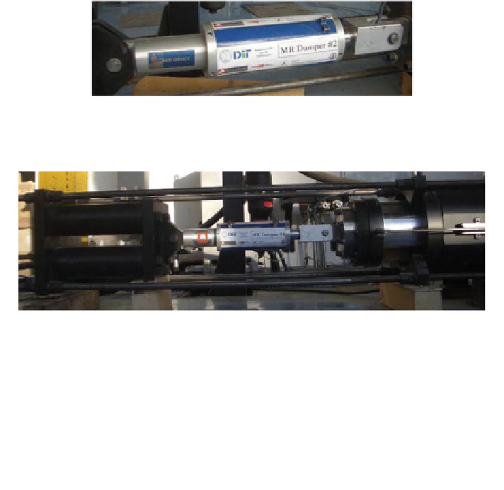
Fig. 13.7
One of the two prototype MR dampers
x
(t)=0
b
x
(t)
LVDT1
tubes
Threaded bars
Load
cell
MR damper
VA
2500 mm
Fig. 13.8
Photograph and sketch of the experimental apparatus
30
30
2.7 A
2.7 A
1.8 A
1.8 A
20
20
0.9 A
0.9 A
10
10
0.0 A
0.0 A
0
0
-20
-15
-10
-5
0
5
10
15
20
-200
-150
-100
-50
0
50
100
150
200
-10
-10
-20
-20
-30
-30
displacement [mm]
velocity [mm/s]
Fig. 13.9
Experimental
response
of
one
MR
damper
under
1.5
Hz,
±20 mm
harmonic
displacement