Environmental Engineering Reference
In-Depth Information
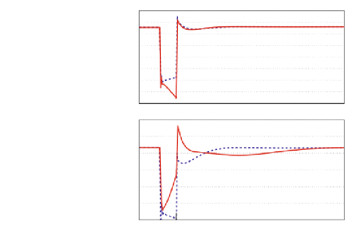
Fig. 1.20 Active and
reactive power from WF to
PCC for three-phase fault
Active power from WF to PCC (pu)
5
4
3
2
1
0
-1
-2
-3
Reactive power from WF to PCC(pu)
1
0.5
Mode1
0
Mode2
-0.5
-1
-1.5
-2
0
0.2
0.4
0.6
0.8
1
1.2
1.4
1.6
1.8
2
Time(sec)
1.5 Conclusion
The chapter presented the modeling and the control design of the variable-speed
WT with a permanent-magnet synchronous generator. A comprehensive dynamic
simulation model was presented and implemented in Matlab/Simulink. The control
scheme facilitates independent control of the active and reactive power to the
imposed set values at variable speed. Moreover, the supervisory reactive-power
control scheme, developed for voltage control at a remote location, takes into
account the power generated by the wind turbine and ensures that the local
operating limits are not exceeded. The information passed to the supervisory
control module is used to calculate the reactive power required from the grid-side
converter to achieve the voltage control objective at the PCC. The supervisory
reactive-power control scheme can be general and is readily extendible to multiple
variable-speed wind turbines, and is also beneficial and cost-effective, compared to
installation of auxiliary devices, which are required when the voltage control
scheme such as power factor control is applied for voltage regulation at the PCC.
Acknowledgment This work was conducted under the framework of Research and Develop-
ment Program of the Korea Institute of Energy Research (KIER) (B4-2453-02)*.