Environmental Engineering Reference
In-Depth Information
15
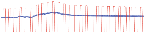
Lower intensity continuous PID
Higher intensity PAM
10
5
0
0
0.5
1
1.5
2
2.5
3
3.5
4
Time (min)
5
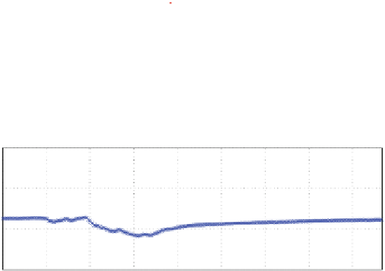
Thermocouple#2 next to PID-controlled resistor
Thermocouple#4 next to PAM-controlled resistor
0
-5
-10
0
0.5
1
1.5
2
2.5
3
3.5
4
Time (min)
Fig. 8.27 a Lower intensity continuous PID controller applied voltage (resistor channel 2) with
the gains K
p
¼
0
:
25 v/(C), K
d
¼
0
:
005 v/(C/s), K
i
¼
0
:
0005 v/(C•s), and PAM applied
voltage (resistor channel 3) with the same electrical energy over one signal period. Both are 10-W
resistors. Lower PID gains are selected compared to the previous subsection (shown in Fig.
8.25
)
to assure that the higher intensity PAM signal is amplified within the operational linear range of
our custom amplifier, before reaching the saturation limit, and to prevent causing large thermal
stresses in the blade structure. b Temperature variation at thermocouple 2 adjacent to resistor
channel 2 with lower intensity continuous PID signal and at thermocouple 4 adjacent to resistor
channel
3
with
higher
intensity
PAM
signal with
the same
amount
of
electrical
energy
expenditure.
The
time
axis
denotes
the
time
after
both
PID
and
PAM
controllers
are
simultaneously turned on
the energy consumption for efficient active de-icing. The feasibility of this method
has been experimentally demonstrated. Development of an aero/thermodynamic
model for a blade with distributed heat sources is extremely beneficial for the
implementation of an optimal closed-loop control as well as for reducing instru-
mentation costs by removing the requirement for temperature sensors on the blade.
However, developing a fully analytical model for such a complex dynamical
system is very difficult, if possible at all.
A computational thermodynamic model for distributed resistive heaters was
developed using ANSYS. This computational model was validated with experi-
mental results using a continuous PID control for thermal actuation. Further,
different heater geometries (square, circular, and hexagonal) for two different
heater layouts (aligned and staggered) were modeled in ANSYS. Our simulations
show faster and more uniform de-icing for circular heaters, and lower thermal
stress to the blade structure for staggered layouts under constant input heat flux to
the resistor network.