Environmental Engineering Reference
In-Depth Information
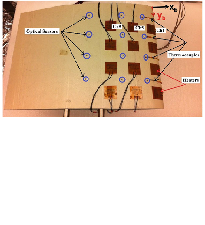
Fig. 8.11 Distributed optical ice sensors, leading edge temperature sensors, and resistive heaters
on a blade segment. Resistor rows are along the y
b
axis, and resistor columns are along the x
b
axis. The optical sensor and the resistor in the top column closest to the blade leading edge are
both labeled as channel 1
Fig. 8.12
Heating elements in: a Aligned array and b Staggered array
this region. The ice/water dynamics including melting and refreezing are poten-
tially quite complex. In Sect.
8.9
, we study the optimization of the layout of
heaters in greater detail. Because of lower relative wind speed, Reynolds number,
convective heat loss, and contribution to power production, the first two-thirds of
the blade (toward the blade root) is less important to be de-iced. Installing dis-
tributed heating elements only on the last third outboard section of the blade
enables decreasing equipment costs and de-icing power consumption while
maintaining 90 % of the aerodynamic performance of the clean blade with only
30 % of the length de-iced [
27
].
Figure
8.13
shows a schematic diagram of the closed-loop control. Numerical
signal processing [
28
] detects the ice existence, type, and thickness by each optical
ice sensor based on the magnitude of the peak, the signal asymmetry, and back-
scatter level. Each optical scan (for all the channels) including numerical detection