Environmental Engineering Reference
In-Depth Information
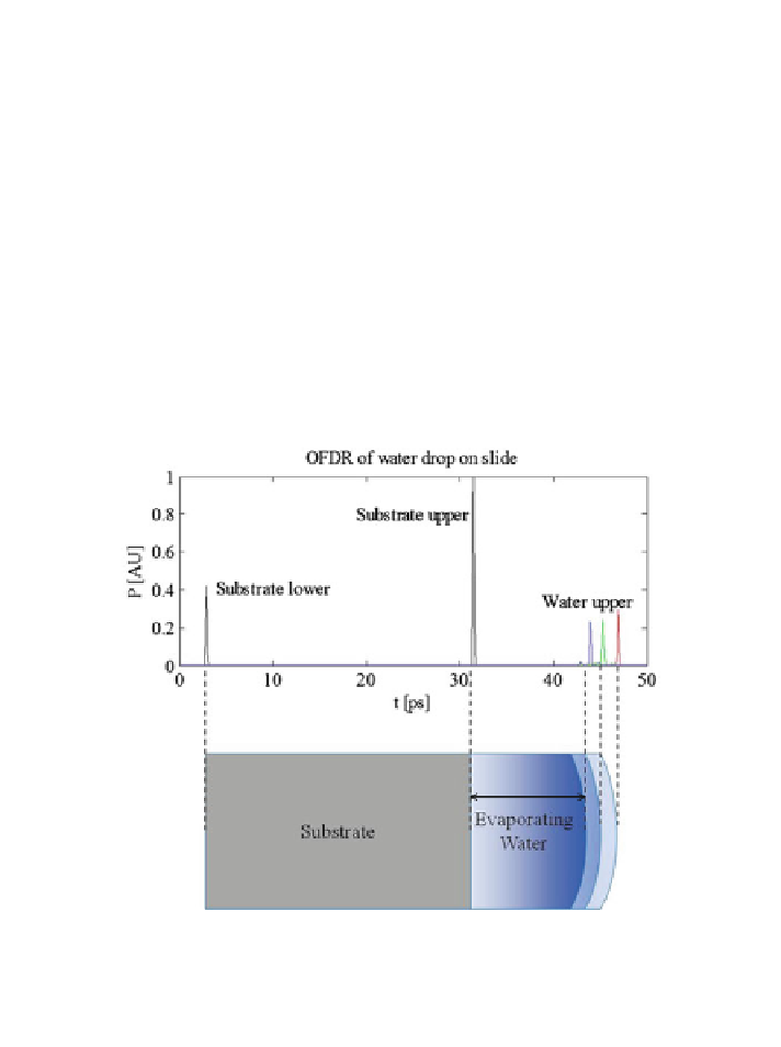
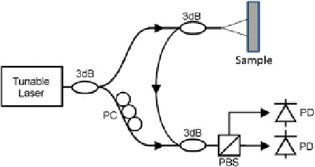
Fig. 8.7 Layout of an optical frequency domain reflectometer [
22
]. Light from the tunable laser
is reflected from the sample and interfered with a reference arm. As the frequency of the laser is
swept, interference fringes are detected that indicate the amplitude and round-trip delay of
reflections
from
the
sample.
3db = 50/50
fiber
coupler,
PC = polarization
controller,
PBS = polarization beam splitter, PD = photodiode
1.86 mm
2.32 mm
Fig. 8.8 Optical frequency domain reflectometry of a variable thickness water layer deposited
on a substrate. The water layer, which was allowed to evaporate over the course of approximately
1 h, was measured at three times to have thickness 2.32, 2.08, and 1.86 mm with a transform-
limited precision of 0.036 mm. The vertical axis is the amplitude of reflection. On the horizontal
axis, 1 ps corresponds to a round-trip travel time for the laser in 112.5 lm of water [
14
]
and the small scattered signal corresponds to the rough ice/air interface. Rime ice
(Fig.
8.9
d) has a highly nonsymmetric shape and distinctive volume scatter due to
the increased air volume within the ice and irregular shape of the ice crystals. These
signals can be recognized and categorized in signal processing to identify type and
thickness. The peak magnitudes and corresponding times where these peaks occur
are numerically calculated. A magnitude filter is applied to reject noise while being