Environmental Engineering Reference
In-Depth Information
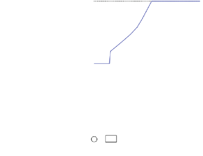
Fig. 1.5 WT maximum
energy-harvesting curve
1
0.8
0.6
0.4
0.2
0
0.5
1
1.5
Generator rotor speed ( , pu)
ω
r
Fig. 1.6 Block diagram of
the generator-side converter
controller
i
d
set
*
v
d
s
v
ds
v
ds
+
P
g
set
PI1
PI2
_
_
+
_
+
P
g
i
ds
ω
e
ψ
qs
v
dc
i
q
set
v
q
s
v
qs
v
qs
*
Q
set
PI3
PI4
+
_
+
+
_
+
i
qs
Q
s
ω
e
ψ
ds
A. Generator-side converter controller: Fig.
1.6
shows a block diagram of the
generator-side converter controller module, which includes four internal PI
controllers, PI1 through PI4. The controller is implemented as two branches,
one for the active power (PI1 and PI2) and one for the reactive power (PI3 and
PI4) with the corresponding de-coupling terms between the d and q axes,
respectively.
The transfer function from the stator voltage to the stator current is approxi-
mated as
T
T
1
R
s
þ
sL
ds
=
x
b
1
R
s
þ
sL
qs
x
b
I
ds
ð
s
Þ
V
ds
ð
s
Þ
I
qs
ð
s
Þ
V
qs
ð
s
Þ
¼
ð
1
:
9
Þ
ð
Þ
Similarly, the transfer function from the stator current to reactive and active
power is approximated as
T
T
P
s
ð
s
Þ
I
ds
ð
s
Þ
Q
g
ð
s
Þ
I
qs
ð
s
Þ
R
s
þ
s
L
qs
x
b
¼
R
s
þ
s
L
ds
x
b
ð
1
:
10
Þ
Then, Eq.
1.9
is used to tune PI2 and PI4, and Eq.
1.10
is used to tune PI1 and
PI3.