Environmental Engineering Reference
In-Depth Information
(a)
TSR
w
ith(out) f
sg
com
p
ensation
11
λ
λ
λ
opt
without fault comp.
with fault comp.
10
9
8
7
effect of f
sg
6
5
0
100
200
300
400
500
600
Time(s)
(b)
TS
R
with(out) f
sg
co
m
pensation
11
10
effect of f
sg
9
8
7
λ
λ
λ
opt
without fault comp.
with fa
u
lt comp.
6
5
0
100
200
300
400
500
600
Time(s)
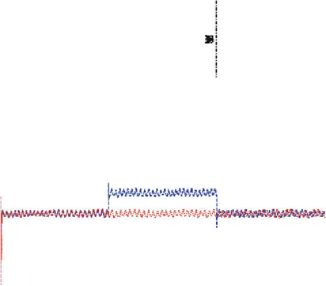
Fig. 7.12
Effect of 1.1 a and 0.9 b sensor scale faults with(out) fault compensation
the proposed strategy to tolerate the effects of sensor faults and maintain optimal
wind turbine operation (Fig.
7.12
).
It is clear that the 1.1 scale sensor fault causes a deceleration of x
r
& x
g
. Based
on the faulty measurement, the controller forces the turbine to reduce the rotational
speed by increasing the reference generator torque (the generator acts with a
breaking torque that can decelerate or release the aerodynamic subsystem) which
in turn increases the drive train load. Hence, although the sensor fault is a scale-up
fault, the actual rotational speeds of the generator and rotor are decelerated as a
result of the dependence of the controller on the faulty measured signal. The effect
of this fault scenario is shown in Fig.
7.13
without sensor fault compensation.
Conversely, the 0.9 scale sensor fault causes acceleration of x
r
& x
g
since,
based on faulty measurement; the controller releases the aerodynamic subsystem