Environmental Engineering Reference
In-Depth Information
Assuming that v can be represented as:
v
2
þ
v
wind
2
¼
v
ð
7
:
14b
Þ
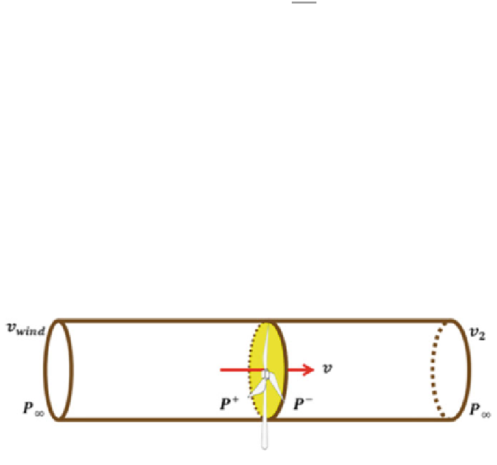
It then follows that the wind speed at the disc v and the downstream wind v
2
are
related to the upstream wind v
wind
as follows:
v
¼
1
ð Þ
v
wind
v
2
¼
1
2a
ð
7
:
15
Þ
ð
Þ
v
wind
where a is known as the axial interference factor defined as the fractional increase
in wind velocity between the free stream and the rotor plane. Using Eqs. (13) and
(15) the power captured by the actuator disc is given by:
P
cap
¼
1
2
q
A
m
3
ð
4a
8a
2
þ
4a
3
Þ
ð
7
:
16
Þ
the maximum power captured is obtained when
d
P
cap
d
a
¼
0, for which a
¼
3
. Hence,
by substituting a in Eq. (
7.16
) the ideal power captured by disc actuator will be:
P
cap
¼
1
2
q
A
m
3
16
27
¼
0
:
59P
wind
ð
7
:
17
Þ
Clearly, the three blade variable speed-variable pitch wind turbines are a special
case of the actuator disc. In this special structure of actuator disc, the blade pitch
angles (b), wind speed (v) and the rotor rotational speed (x
r
) are the main variables
that affect the amount of the power captured. See Fig.
7.6
.
Generally, wind turbine control objectives are functions of wind speed. For low
wind speeds, the objective is to optimise wind power capture through the tracking of
optimal generator speed signals. Once the wind speed increases above its nominal
value the control objective moves to the rated regulating power. See Fig.
7.4
.
Usually, the wind speed and rotor rotational speed x
r
are given in terms of the
tip speed ratio k (or TSR). Hence, the variation of power conversion efficiency with
respect to k and b is given either as a mathematical polynomial or as look-up table.