Environmental Engineering Reference
In-Depth Information
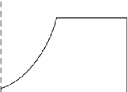
Fig. 6.2 Region of operation
[MW]
I
II
IV
III
5
2.5
3
11.4
25
[m/s]
offshore, some additional vibration modes appear, see Fig.
6.4
. These are much
more low frequent, and the lowest frequencies are in the area 0
:
01
0
:
04 Hz. When
the turbine is designed, the designers already know the wind and wave frequencies
in the area, and design the turbine structure accordingly. This is to make sure that
the surrounding environment will not excite any of the structural vibration modes.
For nonfloating turbines, the soil also plays a major role in relation to the structural
natural frequencies, as discussed in [
2
]. A controller for an onshore turbine, typ-
ically has a frequency of 0.1 Hz, i.e., lower than the tower fore-aft bending mode.
If this controller was implemented on the offshore turbine, then the controller
would be faster than the tower vibration modes. This can cause a stability issue
once the wind speed is above rated. One can quite easily visualize why this
becomes a problem. It is known that, in the above-rated wind speed conditions
the controlling variable is the blade pitch angle. When the wind speed increases,
the blades will pitch out of the wind in order not to gain higher generator speed.
This means that the aerodynamic forces acting on the tower will decrease and it
will start to move forward. It is during this motion the stability issue occurs and it
is directly related to the pitching frequency of the blades. Let us consider two
scenarios: (1) the onshore controller is being used, (2) the offshore controller is
being used. In the first scenario, the blades are being pitched out of the wind at a
higher frequency than the tower is moving forward. The consequence is that the
tower will lose most of its aerodynamic damping. The result is that the tower and
eventually the generator will start to oscillate and eventually become unstable. In
the second scenario, the blades are being pitched out of the wind with a lower
frequency than the tower is moving forward. Therefore, the tower will not loose as
much of the aerodynamic damping, and the overall system will maintain its
stability.
In today's industry, PI or PID controllers are commonly used. These are
designed by keeping in mind these critical frequencies. Pole placement is one way
of getting the closed-loop system poles at the right locations. The control design
proposed in this chapter does not directly include these stability constraints, but
they are indirectly included since the proposed controller design is model based and
guarantees stability. This problem will be demonstrated in the simulation results.