Environmental Engineering Reference
In-Depth Information
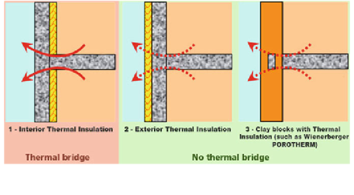
Fig. 5.2
Example of thermal bridge and no thermal bridge in vertical opaque external structures
(Reproduced from Beodom.com)
values must be considered as bounding the average thermal transmittance of the
wall plus the thermal bridging. In Fig.
5.2
an example of a solved thermal bridge is
given.
For vertical opaque external structures where limited areas must show a
reduced thickness, under-windows or other components, the limit must be
respected with reference to the entire calculation surface. For horizontal structures
on the floor the values of U to be compared with the limit have been evaluated with
reference to the system structure-ground. The automated walkable entries are
excluded and they must be considered only to evaluate the changes of air.
It must be noted that if the edifice is built out respecting the limits imposed by
the current legislation (Table
5.2
) acceptable levels of energy performance could
be reached. But a possible improvement of the transmittance of such component
would allow reducing the heat winter losses thanks to a highly sealed envelope and
to the elimination of thermal bridges. An increased sealing of the envelope on the
other hand reduces the air changes of the building envelope, therefore, it may be
required an additional ventilation system (such as for example a forced ventilation
system with heat recovery from exhaust air).
The energy required for winter heating is also reduced if the design includes the
possibility to exploit the solar heat gains through the glass shutters or glass walls
installed on the south oriented walls, in this way heat losses may also be reduced if
the north oriented walls with glass have a more limited surface.
It is also important to underline the energy needs of the building due to summer
cooling, are reduced if the solar earnings of the external surfaces are minimized