Information Technology Reference
In-Depth Information
WxWidgets
OpenSceneGraph
HDF
OpenGl
C++
Fig. 3.7
GIDE architecture
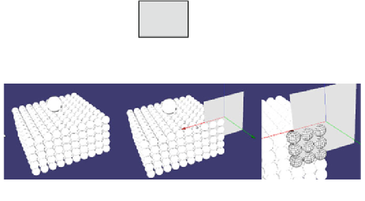
Fig. 3.8
Showing marking of an element
3.3.1 Tracer
In GIDE, a tracer is a visual marker applicable to a body. It enables one or more
bodies to be followed throughout the simulation. To apply a marker a zone of
space is selected. All bodies within this zone will be marked (Fig.
3.8
).
The user has several tools at his disposal, to delimit a zone of space: {the point,
the line, the plane, the cubic volume}. Each of these tools is directly manipulable
with the aid of the mouse. Marking is then done by intersection of the zone with
the set of bodies; all the bodies having an intersection, even partial, with the
defined zone will be marked.
The following example illustrates the marking of a layer in a silo, and its
follow-up during the flowing (Figs.
3.9
,
3.10
,
3.11
and
3.12
).
3.3.2 Sensor
A sensor is defined as an active element. With it, data can be extracted and cal-
culations performed on them. This part is currently limited to applying a calculation
formula to each of the bodies encountered by the sensor and to trace the result.
Search WWH ::

Custom Search