Information Technology Reference
In-Depth Information
Fig. 12.2
Semi-assembled test section
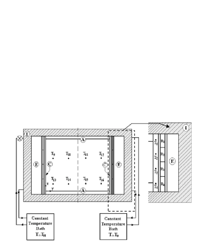
Fig. 12.3
Schematic diagram of the test section
gain from the environment to the experimental apparatus. During the visualization
and photographic observations, part of the insulating material was removed. Dis-
tilled water was used as the testing fluid to avoid the presence of air bubbles. Four
independent and controllable electrical resistances for each copper wall and two
multipass copper heat exchangers were used. Omegatherm 201 conductive paste
was used to ensure good thermal contact between the electrical resistances and the
heat exchangers and the copper wall. The heat exchanger positioned on the side of
the hot wall was connected through a valve system to the constant temperature bath.
Four 0.5 mm thermocouples equally spaced in the z direction were embedded into

Search WWH ::

Custom Search