Hardware Reference
In-Depth Information
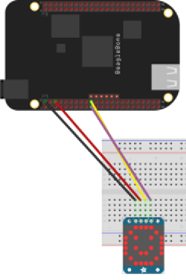
Wiring the matrix to the board
After this short introduction to the I2C protocol, we can now set up the connection
between the two devices, as shown here:
This image is not a drawing. You can obtain the source file from
the GitHub website as a design file in order to use it with
Fritzing
design software.
Assuming that the matrix is now built, we can wire the matrix according to the
following schema:
•
SCL
: Pin 20
•
DAT
: Pin 19
•
+5V
: Pin 6
•
GND
: Pin 2