Graphics Programs Reference
In-Depth Information
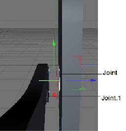
Figure 2-22
The position of Joint and Joint.1 displayed in the Perspective viewport
In the Attribute Manager, make sure that the
Coordinates
area is displayed. In this area,
enter
-24.05
in the
P . Z
spinner. Figure 2-22 shows the position of
Joint
and
Joint.1
in
the Perspective viewport.
Next, you will create the surface of the joints.
11. Press and hold the left mouse button on the
Subdivision Surface
tool in the Command
Palette; a flyout is displayed. Next, choose the
Loft
tool from it;
Loft
is added to the Ob-
ject Manager.
12. Press F5; all viewports are displayed. Select
Joint
and
Joint.1
in the Object Manager by
using the SHIFT key and then press and hold the left mouse button and drag the cursor
on
Loft
; the
Joint
and
Joint.1
are connected to the
Loft
in the Object Manager. Also, a
surface is created. Figure 2-23 displays the surface in all viewports.
Next, you will group the surfaces together.
Search WWH ::

Custom Search