Graphics Programs Reference
In-Depth Information
Figure 13-23
Connection established between
Compare 2
and
Condition 2
nodes
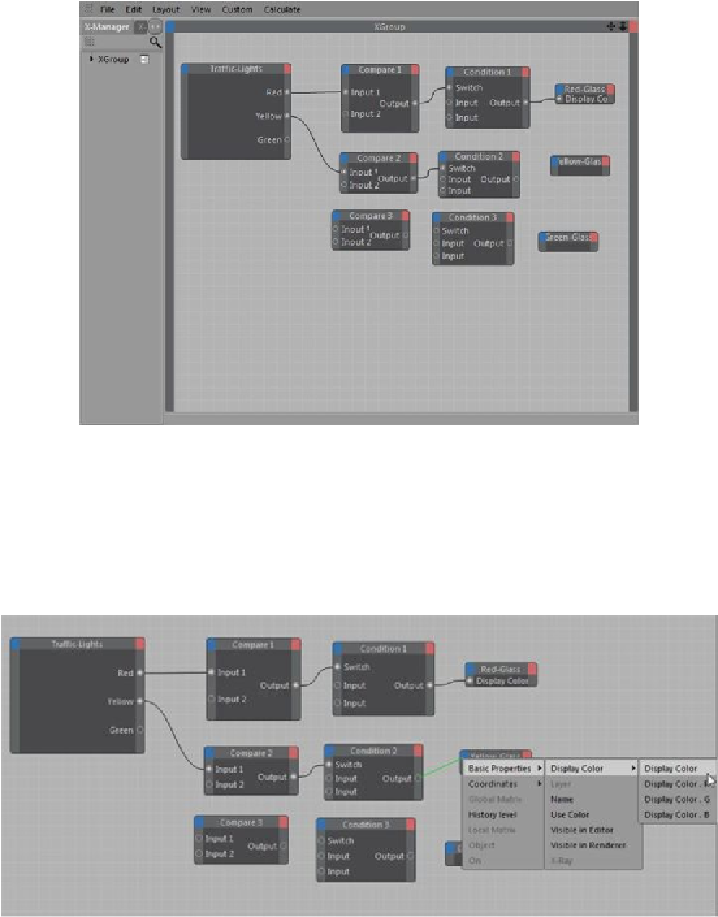
7. In the
XGroup
area, click on the
Output
output port of the
Condition 2
node and drag
the cursor to the input port (blue square) of the
Yellow-Glass
node; a flyout is displayed.
From this flyout, choose
Basic Properties > Display Color > Display Color
, as shown
in Figure 13-24; a connection is established between the
Condition 2
and
Yellow-Glass
nodes. Minimize the
XPresso Editor
.
Figure 13-24
Choosing
Display Color
from the flyout in the
XPresso Editor
Search WWH ::

Custom Search