Graphics Programs Reference
In-Depth Information
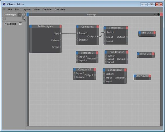
Figure 13-19
Connection established between the
Compare 1
and
Condition 1
nodes
Next, you will connect the
Condition 1
node with the
Red-Glass
node.
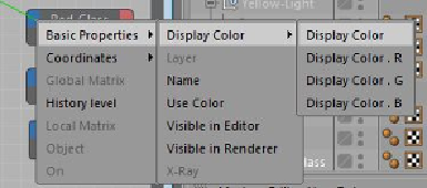
3. In the
XGroup
area, click on the
Output
output port of the
Condition 1
node and drag
the cursor to the input port (blue square) of the
Red-Glass
node; a flyout is displayed.
From this flyout, choose
Basic Properties > Display Color > Display Color
, as shown
in Figure 13-20; a connection is established between the
Condition 1
and the
Red-Glass
nodes. Minimize the
XPresso Editor
.
Figure 13-20
Choosing
Display Color
from the flyout in the
XPresso Editor
4. Select
Traffic-Lights
in the Object Manager. In the Attribute Manager, choose the
User
Data
button; the
User Data
area is displayed. In this area, specify any value greater than
Search WWH ::

Custom Search