Environmental Engineering Reference
In-Depth Information
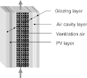
Figure 2.1
Representation of a hybrid solar fa¸ade with seven different layers for the simulation model
and as a type which can be integrated into dynamic building simulation tools (e.g. as
type 111 in TRNSYS).
Generally, a ventilated fa¸ade system consists of an air space between two solid
boundary walls. In the developed simulation model, the solid fa¸ade construction can
be as complex as desired. An example of a possible construction for a hybrid solar
fa¸ade is shown in Figure 2.1.
A PV layer embedded between two glazing layers forms the external boundary and
a double glazing window the internal boundary. The air space between the outer and
inner layers may be ventilated by forced convection or naturally driven flow. Apart
from the construction described above, the following choice of layer types can be
combined arbitrarily:
Massive opaque layer with optional heat sources.
Massive transparent layer (pane) with varying optical properties such as reflectance,
absorptance and transmittance (the optical properties may be used optionally
depending on the incident angle).
Massive PV layer. Semitransparent layer with PV elements, considering converted
electrical power depending on layer temperature.
Ventilated air gap (massless). Consideration of long-wave radiative heat exchange
between adjacent layers as well as convective heat transfer.
Air cavity (massless). Consideration of long-wave radiative heat exchange between
adjacent layers as well as convective heat transfer.
2.2 Experimental Results on Total Energy Transmittance
2.2.1 Laboratory Experiments
The fa¸ade causes additional summer cooling loads through direct transmission of
short-wave irradiance, secondary heat fluxes from the internal surface temperature
Search WWH ::

Custom Search