Environmental Engineering Reference
In-Depth Information
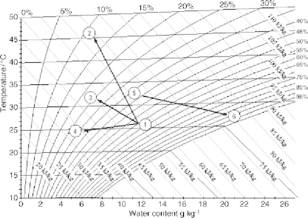
Figure 5.68
Paths of return air dehumidification for different process options
32
◦
C and 40% relative humidity. The results of the measurements taken at an air
volume flow of 200m
3
h
−
1
are shown in Figure 5.68.
Path 1-2 describes the measured dehumidification process in the investigated des-
iccant rotor (AWheel) using regeneration air with a 12 g
water
kg
−
1
air
humidity ratio, at
70
◦
C and volume flows of 187m
3
h
−
1
. The humidity of the return air is reduced in the
desiccant rotor by about 4.3 g
water
kg
−
1
air
, while the temperature of the return air is in-
creased by about 19
◦
C. This significant rise in temperature results from the adsorption
enthalpy and the heat transferred from the regeneration side.
Path 1-3, which indicates the dehumidification of the return air in the contact matrix
absorber unit (CMAU), shows a dehumidification of about 4.2 g
water
kg
−
1
air
combined
with an increase in the return air temperature of about 5
◦
C. A part of the absorp-
tion enthalpy is removed by the liquid desiccant so that the process also reduces the
enthalpy.
Path 1-4 shows themeasured dehumidification of the return air in the heat exchanger
absorber unit (HEAU). The humidity is reduced by about 5.7 g
water
kg
−
1
air
, while the
temperature of the return air is decreased by about 1
◦
C, that is, the process is just
slightly better than isothermal.
Path 5-6 shows the humidification and evaporative cooling process of the ambient
air in the cooling channels of the heat exchanger absorber unit. The humidification
process is also not isenthalpic. This is a consequence of the simultaneous removal of
Search WWH ::

Custom Search