Information Technology Reference
In-Depth Information
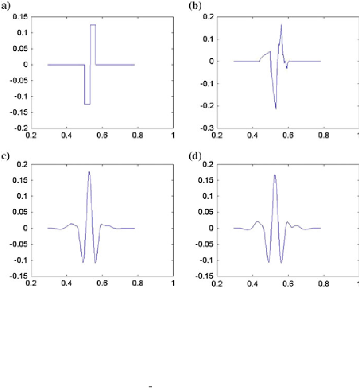
Fig. 9.10
Some wavelets.
a
Haar.
b
Daubechies4.
c
C3 Coi
et.
d
S8 Symmlet
corresponds to the case where
a
0
= 2 and
b
0
= 1. In this case,
j
=1,2,
,
n
, where
n
is the base-2 logarithm of the number of points forming the signal and
k
=1,2,
…
,2
j
−
1
. Then, the dyadic discrete wavelet transform is:
…
Z
1
x
j
;
k
¼
2
2
X
ð
t
Þ
w
ð
2
j
t
k
Þ
dt
ð
9
:
2
Þ
1
where
j
is the decomposition level (or scale) and
k
the time lag. The maximal
number of decomposition levels,
n
, is the log
2
of the number of points forming the
signal. The discrete wavelet transform is faster than the continuous version and also
allows for an exact reconstruction of the original signal by inverse transformation.
The dyadic grid provides a spatial frequency representation of discrete dyadic
wavelet transform (see Fig.
9.11
). In this Figure, the
x
-axis corresponds to time, the
y
-axis represents the frequencies, and the circles correspond to the wavelet coeffi-
-
cients
x
j
,
k
. The signal points are represented below the last level of decomposition.
At each additional level, the frequency is doubled.
The dyadic grid allows us to visualize the frequency content of the signal and to
see when these frequencies appear. For example, Fig.
9.12
represents a signal
and his DWT computed by the toolbox FracLab (Levy Vehel and Legrand
2004
),