Information Technology Reference
In-Depth Information
Objective point
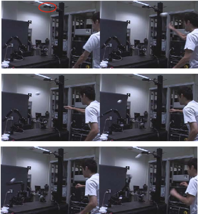
Fig. 3.8
Continuous sequence of batting motion [10]
In this way, even though a simple PD controller is used, the manipulator achieves
high-speed and reactive motion by giving the appropriate desired command. Figures
3.8 and 3.9 are continuous sequences of pictures which were taken at the intervals
of 132 ms and 30 ms respectively.
Figure 3.10 shows the simulation results of the time response of the desired joint
velocity and the desired motor torque when the hitting point moves 10 cm during
the swing motion. The desired joint velocity
ω
d
and the desired motor torque
τ
d
are
computed as
ω
d
=
q
d
,
(3.15)
τ
d
=
M
(
q
d
)
q
d
+
h
(
q
d
,
q
d
)+
g
(
q
d
)
.
(3.16)
Even in this case, a smooth trajectory is generated which is similar to the trajec-
tory in the case of the fixed hitting point. The change of torque is continuous, but
not smooth at the start time and the hitting time. This is because the polynomial
Search WWH ::

Custom Search