Information Technology Reference
In-Depth Information
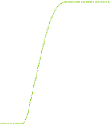
Arm shape
Bat trajectory
1.3
Objective point
1
0.7
0.4
0.1
1.3
Ball trajectory before impact
1
-0.2
Ball trajectory after impact
0.
7
Predicted ball trajectory
-0.5
0.
4
y [m]
-0.5
0
0.1
0.5
1
1.5
2
x [m]
Fig. 3.6
Batting motion [10]
Observed
trajectory
Modified
trajectory
based on
p
01
(
t
b
)
Desired
trajectory
based on
p
0N
(
t
b
)
4
1.
Observed
trajectory
Desired
trajectory
time [s]
time [s]
(a) SW mode (joint 1)
(b) HT mode (joint 4)
Fig. 3.7
Time response of joint angles [10]
The velocity of the ball is 6
∼
8 m/s, and the velocity of the end-effector is about 6
m/s at the impact point.
Figure 3.6 shows the motion of the arm and ball. The ball is recognized at
x
= 2
.
1
m and is hit on the hitting point at
x
= 0
33 m. From the data for the ball position
after hitting, it turns out that the hit ball heads in the direction to the objective point.
The time response of joint angles is shown in Figure 3.7. It turns out that the smooth
joint trajectory is generated in either mode. In HT mode (the joint 4), the desired
trajectory based on
p
01
(
t
b
) is modified to that based on
p
0
N
(
t
b
) (
N
= 250) due to the
shift of the hitting point. Then the actual trajectory of the manipulator tracks it. This
result means that the manipulator can hit a breaking ball.
.


Search WWH ::

Custom Search