Information Technology Reference
In-Depth Information
(a)
(b)
1
0.15
0
0.1
−1
0.05
−2
−3
0
−4
−0.05
−5
−0.1
−6
−7
200
400
600
800
1000
1200
1400
200
400
600
800
1000
1200
1400
(c)
(d)
0.5
0
0.4
0.3
0.2
−50
0.1
0
−0.1
−100
−0.2
−0.3
−0.4
−0.5
−150
200
400
600
800
1000
1200
1400
200
400
600
800
1000
1200
1400
(e)
(f)
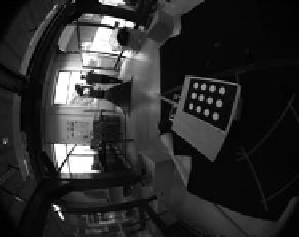
Fig. 16.4 B
, 2 1/2 D visual servoing: (a) initial image; (b) desired image and image-points
trajectories; (c) translational velocities in
m
/
s
; (d) rotational velocities in
deg
/
s
; and (e) error
vector components
ρ
i
(which appears in the interaction matrix (16.11)) are set to a constant values
ρ
i
= ρ
i
(where
ρ
i
denotes the estimated value of
ρ
i
at the desired configuration).
Consequently, the points trajectories are no more straight lines until around the 300
th
iteration (where
ρ
i
). After the 300
th
iteration, one can ob-
serve that the errors are decreasing exponentially and the image trajectories became
roughly straight.
The results obtained with the hybrid control
B
,
C
and
D
are shown in Figures
16.4, 16.5 and 16.6 respectively. The parameter
ρ
i
became very close to
ρ
is set to ρ
= 2
ρ
in those cases.


Search WWH ::

Custom Search