Information Technology Reference
In-Depth Information
10.5
Case Study
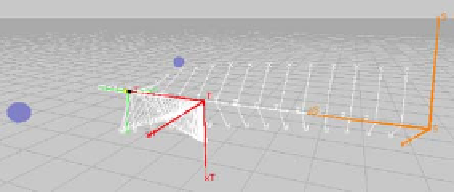
The image-based positioning of a 2 DOF camera with respect to a still target
is considered (Figure 10.2). The camera can move along and around its optical
axis, so that
u
and
x
write as
u
=(
v
z
ω
z
)
and
x
=(
t
z
N
tan(
4
)
)
. Its focal length is
normalized to
f
= 1. The target is fitted with two asymmetric spots
T
1
,
T
2
character-
ized by
z
S
=
z
T
,
a
1
=
a
2
= 0,
b
1
= 1,
b
2
=
−
2,
c
1
=
c
2
=
c
= 1
.
5. The visual feed-
back
u
=
−
λ[
J
(
s
∗
,
z
∗
)]
+
(
s
s
∗
) described in [14, 3] is implemented, with
−
λ = 0
.
1,
z
∗
=(
cc
)
and
z
∗
) the interaction matrix computed at the reference situation.
As the controller is static,
x
=
x
holds, and the closed-loop state equation writes as
(
s
∗
,
J
⎛
⎞
⎠
t
N
.
8
c
2
N
(1+
N
2
)
2
0
−
c
(1
−
N
2
)
(1+
N
2
)
t
N
=
λ
−
−
c
⎝
(10.52)
t
z
+
c
s
−
1
No 3D constraint is imposed on the motion. The actuators limits are
|
v
z
|≤
1
.
5m
.
s
−
1
.For
f
= 1, the virtual limits of the image plane are set to
and
|
ω
z
|≤
1rad
.
|
x
i
|≤
4m and
|
y
i
|≤
3 m. These constraints are expressed thanks to the following
s
∗
=
(
s
∗
,
z
∗
)]
+
:
−
C
(
x
)
x
and of the controller gain
K
−
λ
J
expressions of
y
=
s
=
[
⎛
⎞
⎠
t
N
;
=
−
λ
c
ca
1
4
b
i
N
2
x
i
−
x
∗
i
y
i
−
=
a
i
c
i
−
8
a
i
N
−
4
b
i
(1+
N
2
)
2
cb
1
ca
2
cb
2
−
⎝
b
1
−
a
1
b
2
−
a
2
1
t
z
+
c
i
K
.
y
∗
i
4
a
i
N
2
a
1
+
b
1
+
a
2
+
b
2
b
i
c
i
−
8
b
i
N
+4
a
i
(1+
N
2
)
2
−
−
(10.53)
As per [3], the convergence fails if
N
= 1 at initial time. Note that despite its appar-
ent simplicity, the exact
multicriteria
basin of attraction of this 2D servo is unknown.
First,
˜
∪
r
∈
Ξ
R
(
˜
)
r
of elementary multicriteria basins
of attraction computed through separate optimization problems as suggested in
Section 10.3.1.3. BQLFs of the form
V
(
x
)=(
t
z
,
E
is defined as the union
E
N
)
P
N
2
(
t
z
,
N
2
t
z
N
,
,
t
z
,
t
z
N
,
,
t
z
,
N
)
Θ
are considered,
i.e.
the matrix function
Θ
(
x
,
χ
) and
(
x
,
χ
) are set to
Θ
(
x
,
χ
)=
0
t
z
t
z
2
N
. The results are shown on
Figure 10.3, endowed with an horizontal
t
z
-axis and a vertical
N
-axis. The admissi-
ble subset of the state space is the area on the right of the left vertical curves, defined
from the actuators and visibility constraints.
(
x
)=
2
t
z
NN
0
(
x
)=(
t
z
I
2
N
I
2
)
and
Θ
)=
Θ
Θ
(
x
,
χ
Fig. 10.2
2 DOF image-
based control


Search WWH ::

Custom Search