Information Technology Reference
In-Depth Information
Simulated
instrument
LED
d
center of mass
attached to the organ
y
Δ
x
of the markers
Δ
Laser spot
(from the instrument)
markers attached
to the organ
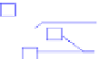
Fig. 6.11
Heart-tool synchronization experimental testbed
5
gear-heads. The actuators have
been chosen such that their power is high enough to be compatible with the heart
motion dynamics. In order to validate the heart motion compensation approach, only
the three first joints of the robots are used.
The position of the robot tip with respect to the beating heart is measured thanks
to a high speed camera acquiring artificial markers at 500 fps. Indeed four light
emitting diodes (LEDs) are used: three are attached to the heart surface while an-
other one is affixed on the instrument tip. Moreover, the instrument embeds a laser
source which projects a beam parallel to the instrument axis, yielding a spot on the
beating heart. As shown in Figure 6.11, we can define a vector of visual features
F
=[
d
using brushless motors with Harmonic Drive
R
Δ
x
Δ
y
] that fully describes the relative position between the heart and the
surgical instrument. Servoing
F
=[
d
Δ
x
Δ
y
]
T
to
F
∗
=[
d
∗
00] yields a synchroniza-
tion between the heart and the robot motion and a constant relative position between
the instrument and the operation area. The visual servo-loop, synchronized with im-
age acquisition, is implemented in a real-time mode on a vision computer hosting
the frame grabber. The vision computer performs the image acquisition, image pro-
cessing and control signals computing. The computed control signals are sent to the
robot controller via a 10 Mb/s serial link.
The visual servoing loop is given in Figure 6.12. The computed control law
U
(
z
)
is delayed by one sample to model the fast serial link transfer, and then converted
into an analog voltage
Q
∗
with a digital-analog converter modeled by a zero-order
hold (ZOH).
Q
∗
is then sent as a reference to the joint velocity loops of the robot.
The dynamics of these loops are assumed to be almost linear around the current
working point and so are modeled by a transfer matrix
G
(
s
). The relationship be-
tween the current joint velocity vector
Q
(
s
) and the image velocity vector
F
(
s
) is
given by
J
i
, the interaction matrix. The integrator between
F
(
s
) and
F
(
s
) models
5
Harmonic Drive
R
is a registered trademark of Harmonic Drive LLC.
http://www.harmonicdrive.net


Search WWH ::

Custom Search