Environmental Engineering Reference
In-Depth Information
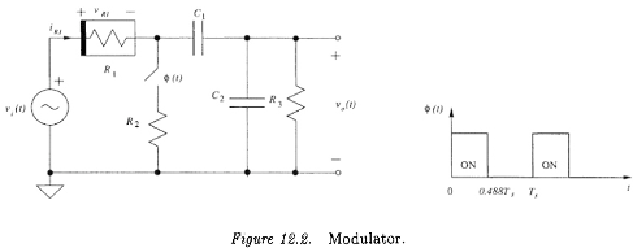
Consider the modulator shown in Fig.12.2 with the parameter values
given in Table 12.2 [141]. The nonlinear resistor
is modeled as a
nonlinear current-controlled voltage source
The circuit was solved using the method presented in the preceding
sections and results are shown in Table 12.3, together with those from
transient-FFT SPICE simulation of SPICE. Care was taken in choosing
the step size in the transient analysis, collecting steady-state response
data, and selecting the number of data points and windows in transient-
FFT analyses of the modulator using SPICE [142, 143, 68]. As observed
that the results compare well with those from SPICE.
To demonstrate the fold-over effect in distortion analysis of period-
ically switched nonlinear circuits, the dependence of the second-order
harmonic components at 1 kHz on the number of side bands consid-
ered is plotted in Fig.12.3. It is seen that the second-order harmonic
component of the response of the modulator converges rapidly.
5.2 Stray-Insensitive Switched Capacitor
Integrator
Consider the stray-insensitive switched capacitor integrator shown
in Fig.12.4 with parameters given in Table 12.4. MOSFET switches
and
are modeled as a linear resistor of resistance
in
series with an ideal switch.
is modeled as a nonlinear resistor in


Search WWH ::

Custom Search