Environmental Engineering Reference
In-Depth Information
7.3 General Periodically Switched Nonlinear
Circuits
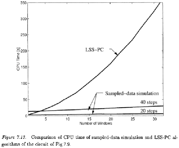
Consider the circuit shown in Fig.7.17 that contains two externally
clocked switches. The clock phases are non-overlapping. The voltages
of the two capacitors are well defined inside either clock phases but
discontinue at switching instants. The clock frequency of the circuit is
5 Hz. Each clock period has two phases of equal width. Zero initial
conditions were assumed for all capacitors. The nonlinear conductor
was modeled as
where
are constants and their values are given by
The input was a unit step current source. To simplify
the simulation, the width of the simulation window was set to be the
same as that of the clock phase. The number of samples per window


Search WWH ::

Custom Search