Geoscience Reference
In-Depth Information
z
k
r
i
+1
r
i
r
i−
1
θ
i
B
i
Δ
r
r
3
r
2
r
1
ψ
k
x
y
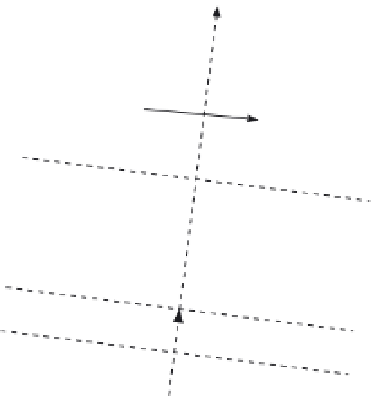
Fig. 13. Geometry of wave propagation in an inhomogeneous magnetized ionosphere.
ˆ
ˆ
Using the components of (65), we can re-express the outgoing electric field phasor
E
θ
θ
+
E
φ
φ
as
e
−
jk
o
nr
e
−
jk
o
Δ
nr
p
O
p
O
+
e
jk
o
Δ
nr
p
X
p
X
E
o
,
E
t
=
(66)
where
E
o
is the wave field at the origin,
ˆ
ja
ˆ
ja
ˆ
ˆ
θ
−
p
X
=
−
θ
+
φ
φ
p
O
=
√
1
√
1
and
(67)
+
a
2
+
a
2
p
O
and
p
X
refer
are the orthonormal polarization vectors of the O- and X-mode waves, while
to their conjugate transpose counterparts.
9.2 Model for radiowave propagation in an inhomogeneous ionosphere
A radiowave propagating through an inhomogeneous magnetoplasma will experience
refraction and polarization effects. At VHF frequencies, however, ionospheric refraction
effects can be considered negligible for most propagation directions because the wave
frequency
1).
But for the same set of frequencies, polarization changes are still significant despite the fact
that the electron gyrofrequency
Ω
e
is much smaller than the wave frequency
ω
ω
exceeds the ionospheric plasma frequency
ω
p
by a wide margin (i.e.,
X
1).
The reason for this is that the distances traveled by the propagating fields are long enough
(hundreds of kilometers) so that phase differences between wave components propagating
in distinct modes accumulate to significant and detectable levels. Taking these elements into
consideration and noting that, at VHF frequencies, the longitudinal components of the wave
fields are negligibly small (as
X
(i.e.,
Y
1), waves propagating through the ionosphere
can be represented as TEM (transverse electromagnetic) waves.
1 and
Y
Consider plane wave propagation in an inhomogeneous magnetized ionosphere in an
arbitrary direction
k
. To model the electric field of the propagating wave, we can divide the