Geoscience Reference
In-Depth Information
Δ
Rain rate [mm/h]
b
a
A = 52
Model
0.02
0.02
13
0.01
0.015
11
0
6
8
10
12
14
Range bin
0.01
9
c
R = 7
R = 8
0.02
0.005
7
0.01
5
0
0
45
47
49
51
53
55
57
59
45
50
55
Azimuth gate
Azimuth gate
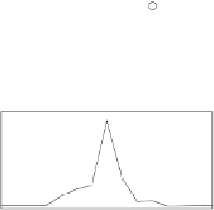
Fig. 6. Wind turbine clutter caused by a wind farm approximately 13 km northeast of the
Karlskrona weather radar. a) Clutter from an area containing five wind turbines (shown by
white asterisks). One wind turbine is located in radar cell [7,49], three are located in [7,52],
and one in [7,55]. b) Clutter from azimuth gate 52 together with model results. c) Clutter
from range bins 7 and 8.
3.1.2 Models
Most models of wind turbine clutter rely on the turbines' radar cross section (RCS) as a
measure of how efficiently radar pulses are backscattered (Agence National des Fréquences,
2005; Tristant, 2006a). In order to model wind turbine clutter the RCS of a wind turbine must
be converted to the equivalent radar reflectivity factor. The radar equation for point targets is
given by (see, e.g. Skolnik (2008))
P
t
G
2
2
λ
σ
=
P
r
(1)
64
π
3
D
4
where
P
r
and
P
t
are, respectively, the power received and transmitted by the radar,
G
is the
antenna gain,
λ
is the wavelength,
σ
is the RCS of the target, and
D
is the distance from the
radar to the target.
For distributed targets, such as rain, the radar equation is written as (see, e.g. Keeler & Serafin
(2008))
P
t
G
2
3
2
z
θφ
c
τπ
|
K
|
P
r
=
(2)
(
)
λ
2
D
2
1024 ln
2
θ
φ
τ
where
and
are the azimuth and elevation beamwidths,
c
is the speed of light,
is the radar
2
is a parameter related to the complex index of refraction of the material, and
z
is the linear radar reflectivity factor. For a given RCS the linear radar reflectivity factor can
thus be expressed as
|
|
pulse width,
K
C
1
D
2
z
=
(3)
where
C
1
is a constant that depends on the parameters of the radar system. For Swedish
weather radars,
C
1
=
10
12
mm
6
m
−
3
.
×
3