Geoscience Reference
In-Depth Information
factor measurements by adding 1 to 4 dB depending on the degree of occultation. The
correction is also applied to all pixels further out in range of the same blocked radar ray,
neglecting diffraction below shadow boundary. The correction depends only on the
percentage of beam cross section shielded and, in the description provided by Fulton et al.
(1998), no specific mention is made about which part of the beam is shielded. This approach
allows consideration of a simple interception function, as the one proposed in the previous
section, assuming that the correction additive factors contain considerations about
interception details such as the beam power distribution. This beam blockage procedure is
used with other corrections such as a test on the vertical echo continuity and a sectorized
hybrid scan (Shedd et al., 1991). Other approaches to this question with different degrees of
sophistication have been used in the past (see for example Delrieu et al. 1995, Gabella and
Perona 1998, Michelson et al. 2000, Park et al. 2009). All of them have in common the
assumption of standard propagation conditions of the radar beam.
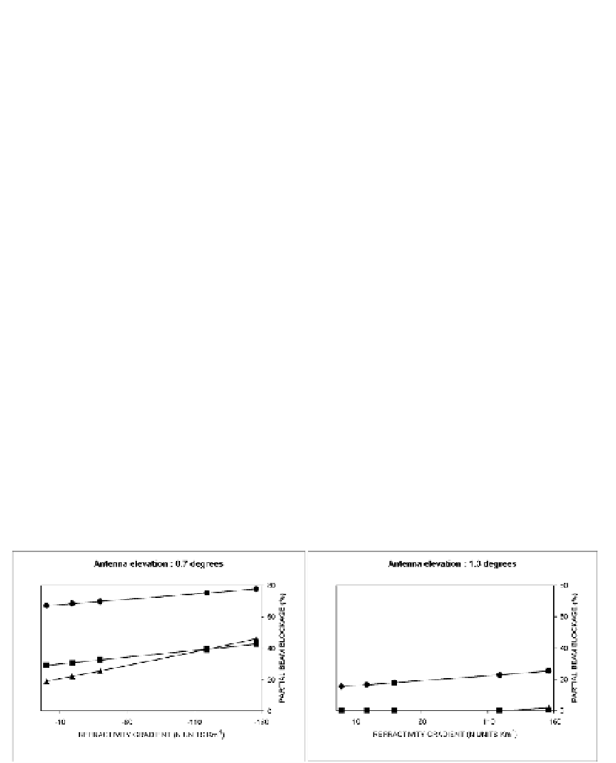
4.4 Refractivity gradient vs beam blockage
The radar beam blockage under a particular VRG can be simulated considering both the
observed propagation conditions and the interception function described in the previous
sections. This may be achieved by assuming an homogeneous VRG for the whole radar
beam and calculating the associated beam blockage for each selected target for a given initial
antenna elevation angle.
In Fig. 11 a set of beam blockages vs VRG plots is shown for different antenna elevation
angles. The refractivity gradient values considered contain the observed extreme VRG
values (-119 km
-1
and -15 km
-1
) and are also extended to include pure subrefraction (0 km
-1
)
and almost ducting conditions (-156 km
-1
) to illustrate their effects. These extreme cases
seem realistic taking into account the presence of thin ducting layers that may have high
VRG embedded in others with lower VRG and considering the fact that the bending of the
ray path is an additive process throughout the whole layer crossed by the radar beam.
Fig. 11. Simulated beam blockage vs vertical refractivity gradient for targets MNT, (circle),
LML (square) and MNY (triangle) at different antenna elevation angles.
As expected, as the antenna angle increases, beam blockage is reduced. For example, for an
antenna elevation of 0.7 º a relatively high beam blockage rate is expected as the lowest part
of the main lobe in a 1.3º beam width antenna is pointing to the surrounding hills,