Environmental Engineering Reference
In-Depth Information
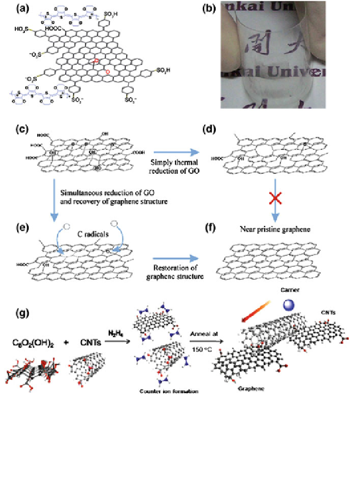
Fig. 4.3 (a) Schematic representation of part of the structure of graphene-PEDOT. (b) A picture
of a graphene-PEDOT film with a thickness of *32 nm on a transparent PMMA substrate. (c-f).
Structure of GO (c) and thermally reduced GO (d); Simultaneous reduction of GO and recovery of
graphene structure (e), to obtain near pristine graphene (f). (g) Scheme of the composite of CNT
and GO. (a-b) Reproduced with permission [
37
]. Copyright 2009, Springer (c-f) Reproduced with
permission [
38
]. Copyright 2011,(g) Reproduced with permission [
39
]. Copyright 2009,ACS
was observed: the values of U
w
of the rGO-SWCNT electrodes decreased from
4.6 eV when doped with Li
2
CO
3
to 3.4 eV when doped with Cs
2
CO
3
(Fig.
4.4
b).
The formation of interfacial dipoles was presumed to be the reason for decreasing
the work function of the rGO-SWCNT composites. Inverted P3HT/PCBM solar
cells employing Cs
2
CO
3
doped rGO-SWCNTs as transparent electrode (transpar-
ency 65.8 % at 550 nm and sheet resistance 331 X/sq) was fabricated and gave
Search WWH ::

Custom Search