Environmental Engineering Reference
In-Depth Information
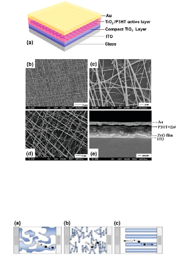
Fig. 9.9 a Schematic of the TiO
2
nanofiber/P3HT device. b low magnification, c high
magnification, SEM images of the electrospun TiO
2
network. d SEM image of electrospun ZnO
network. e SEM cross-section view of the ZnO nanofiber/P3HT device. a, b, c reproduced with
permission from Ref. [
22
], d, e reproduced with permission from Ref. [
31
]
Fig. 9.10
Schematic
illustrations
of
charge
transport
pathways
in
a
polymer
blend
cell.
b nanorod-polymer
cell. c ordered heterojunction
cell. Reproduced with permission
from
Ref. [
77
]
Search WWH ::

Custom Search