Environmental Engineering Reference
In-Depth Information
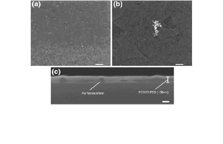
Fig. 8.3 SEM images of the surface of PEDOT:PSS:Au NPs films with a Au NPs capped with
PEG, b Au NPs not capped with PEG. The white bars in (a) and (b) are approximately 200 nm
long. c SEM image of the cross-section of a PEDOT:PSS:Au NPs film, with Au NPs capped with
PEG. The white bar in (c) is approximately 30 nm long. Note that the image is focused on the
cross-section surface of PEDOT:PSS and the Au NPs might be out of focus [
18
]
observed no discernible difference in the performance. Therefore, PEG itself does
not exert any significant effects on our device performances. The contribution of
PEG is to prevent formation of aggregation sites and allow the uniform dispersion
of Au NPs. In the following discussion, the effects of PEG capped Au NPs on
OSCs will be described.
The positioning of Au NPs along with the vertical profile of the PEDOT:PSS
film is shown in Fig.
8.3
c. It can be seen that the majority of the bulk of individual
NPs are located within the PEDOT:PSS layer. At the locations of Au NPs, bumps
are created on the surface of PEDOT:PSS. However, the Au NPs at the bumps are
covered by a layer of PEDOT:PSS and no bare Au NP protrusions are reported in
measurements.
8.2.3 Plasmonic Effects
The LSPR effects can be investigated from the absorption spectrum of the PE-
DOT:PSS/P3HT:PCBM films, with or without Au NPs in PEDOT:PSS as shown
in Fig.
8.4
a. Interestingly, no significant difference is observed in absorption
between the samples with and without Au NPs. Theoretical studies [
16
] have also
been conducted to understand plasmonic effects of Au NPs in the devices [
18
].
The theoretical enhancement factor (i.e., the ratio of the active layer light
absorption of the PEDOT:PSS:Au NPs device over that of the conventional PE-
DOT:PSS one) shows no clear absorption enhancement, with a value around 1 as
shown in the inset of Fig.
8.4
a which agrees well with the experimental results.
Search WWH ::

Custom Search