Biomedical Engineering Reference
In-Depth Information
A
B
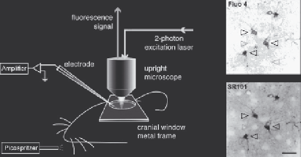
Fig. 5.2. Diagrams of experimental setup. (
A
) A cranial window was opened on the
primary somatosensory cortex. A metal frame was glued to the skull to prevent the
movement of the brain. Whisker stimulation was performed in the contra lateral side
of the animal's snout by air puffs which were generated from a high pressure nitro-
gen tank and control by picospritzer. A plastic tube connected to the picospritzer was
placed ∼2 cm away from the C6 whisker in a rostral-caudal direction to deliver the
high pressure air. Electrical field potential recording and 2-photon Ca
2
+
imaging were
performed simultaneously during whisker stimulation. Agarose (1%) was poured onto
the pial surface before the coverglass was mounted to the metal frame to minimize the
brain pulsation. (
B
) Dual labeling of barrel cortex with Ca
2
+
indicator fluo-4 AM (top)and
astrocyte specific marker SR101 (bottom). Only SR101 positive astrocytes were labeled
with fluo-4 AM (white arrowheads). Neurons appear as dark, round areas without either
fluo-4 AM or SR101 labeling (grayarrowheads). The image shown was located 120 μm
below the pial surface. Scale bar, 30 μm.
respiration rate was set at
∼
100/min; inspiration time, 0.3 s; and
the tidal volume,
0.2 ml. Lung pressure was carefully moni-
tored and maintained at lower than 10 cm H2O to prevent lung
injury. Blood gas was tested by taking arterial blood through a
femoral artery catheter and pCO
2
,pO
2
and pH were analyzed
in microsamples (Rapidlab 248, Bayer, sample size 40
∼
l). Blood
samples were taken every 1-2 h and totally 3-4 times from each
animal. Experiments were completed only if physiological vari-
ables remained within the normal limits. The normal limits for
pCO
2
were set at 30-45 mm Hg; pO
2
, 80-115 mm Hg; and
pH, 7.35-7.45. To image astrocytic Ca
2
+
signals in mouse barrel
cortex, a cranial window (2-3 mm in diameter) was prepared cen-
tered at 0.5 mm posterior to the bregma and 3.5 mm lateral from
midline. To stabilize the brain during imaging, a custom-made
metal plate was glued to the skull with dental acrylic cement. Dura
matter was removed for surface loading of fluorescent indicators.
Body temperature was monitored by a rectal probe and main-
tained at 37
◦
C by a heating blanket (BS4, Harvard Apparatus).
μ
4.2. Ca
2
+
Indicators
Loading
The major difference comparing surface bulk loading and local
dye injection is that the former loading procedure only labels