Environmental Engineering Reference
In-Depth Information
Q
2KbJ
y
x
= − tan
2
p
KbJ
Q
y
∞
=
y
streamline
regional
ow
y
φ
well
capture zone
stagnation point
x
boundary of capture zone
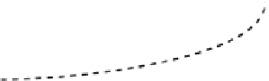
Figure 5.22.
Single extraction well in regional flow.
Therefore, since the width of the capture zone is 2
y
,
the maximum width of the capture zone,
W
1,max
is
given by
y
x
2π
KbJ
Q
= −
tan
y
(5.108)
where
K
is the hydraulic conductivity of the aquifer
(LT
−1
),
b
is the saturated thickness of the aquifer (L),
Q
is the well pumping rate (L3T−1),
3
T
−1
), and
J
is the piezo-
metric gradient in the absence of pumping (dimension-
less). In unconfined aquifers,
J
can be approximated by
the slope of the water table in the absence of pumping
(i.e., the regional gradient). Equation (5.108) assumes
that the aquifer is homogeneous, isotropic, uniform in
cross section, infinite width, and that the intake to the
extraction well extends over the entire saturated thick-
ness. Although these assumptions are seldom met
exactly, they provide close enough approximations in
many cases such that Equation (5.108) provides a rea-
sonable approximation to reality. If
ϕ
represents the
angle (in radians) between the origin (i.e., where the
pumping well is located) and a point on the capture
zone curve, then
Q
KbJ
Q
KbJ
=
(5.112)
W
,max
=
2
1
2
It is apparent from Equation (5.112) that for any
given aquifer, the maximum width of the capture zone,
W
1,max
, is directly proportional to the pumping rate,
Q
,
indicating that the width of the capture zone can be
widened by increasing the pumping rate. However,
increased pumping rates cause increased drawdowns,
and allowable drawdowns generally limit the maximum
pumping rate that can be used. Consequently, there is a
limit of the extent to which the width of the capture
zone can be increased by increasing the pumping rate
from a single extraction well. Also, in some cases, the
available or desired distance between the extraction
well and the contaminated area might be such that the
width of the capture zone over the contaminated area
is less than the maximum width given by Equation
(5.112). For example, the contaminated area and the
extraction well might need to be within existing prop-
erty lines, which would limit the distance between the
extraction well and the contaminated area, or it might
be undesirable to have a large volume of uncontami-
nated groundwater between the extraction well and the
contaminated groundwater, which would require need-
lessly extracting a large volume of clean water and
thereby increasing the time and cost required to clean
up the contaminated area. In cases where the width of
the contaminated area exceeds the width of the capture
zone, multiple extraction wells can be used to widen the
width of the capture zone.
Cases where two and three extractions wells are used
are shown in Figure 5.23. In the case of two extraction
tanφ=
y
x
(5.109)
Combining Equations (5.108) and (5.109) gives the
following alternate equation of the boundary of the
capture zone
Q
KbJ
φ
π
y
=
1
−
,
0
≤ ≤
φ
2
π
(5.110)
2
As
x
→ ∞, Equation (5.109) gives
ϕ
→ 0, and Equa-
tion (5.110) gives
Q
KbJ
(5.111)
y
=
2


Search WWH ::

Custom Search