Environmental Engineering Reference
In-Depth Information
compounds, such as PCBs and some pesticides, and an
example of soil excavation is shown in Figure 5.19. The
costs associated with excavation and removal of large
volumes of soil to another site are usually high, and on-
site treatment of soils, called
ex situ treatment
, should
always be considered as an option. On-site (ex situ)
treatment usually involves processes to remove the
contaminant(s) from the soil and replace the treated soil
at the site. Ex situ treatment techniques include soil
washing, biomounding, low temperature thermal desorp-
tion, and high temperature incineration. For large quan-
tities of contaminated soil, a common reclamation
method involves soil excavation and deposition in a
bioreactor, where biodegradation of the contaminant is
achieved in a comparatively short period of time. This
requires controlling the appropriate supply of moisture,
oxygen, and nutrients for the enhancement of microor-
ganism development and growth. Total excavation of
contaminated soils is sometimes not practical, such as
when contamination penetrates deep into the subsur-
face, contaminants occur beneath a building, or nAPLs
are present.
5.8.2.3 Soil Vapor Extraction.
Soil vapor extraction
(SVE) systems are designed to maximize contaminant
removal by volatization. These systems extract air from
the vadose zone with blowers or vacuum pumps, and
treatment systems above ground remove toxic vapors
from the extracted air. SVE systems are frequently used
to remove volatile contaminants from permeable soils
and are analogous to pump-and-treat systems for
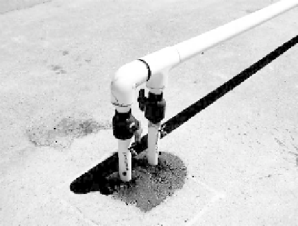
groundwater. A schematic diagram of a SVE system is
shown in Figure 5.20a, and a typical aboveground view
of vapor extraction pipeline as it exits the ground is
shown in Figure 5.20b. In spills of complex solvent mix-
tures, such as gasoline, SVE removes the components
with higher vapor pressures first. The advantages of
using an SVE system are that it creates minimal distur-
bance of the contaminated soil, it can be constructed
from standard equipment, it is cost-effective, and it is
flexible in that several variables can be adjusted during
design or operation. Extraction wells are typically
designed to fully penetrate the vadose zone and to
extend below the water table. Penetration of the water
table allows for seasonal declines in the water table
elevation and declines caused by pumping. Extraction
wells typically consist of an upper 1.5 m (5 ft) of solid
plastic casing connected to slotted plastic pipe placed in
permeable packing. The borehole is typically augured
and sealed around the casing to the top of the borehole
Figure 5.19.
Soil excavation at a Superfund site.
Source
: U.S.
Army Corps of Engineers (2005b).
off-gas
treatment
g
round surface
air flow
air flow
contaminated
soil
water
table
(a)
(b)
Figure 5.20.
Soil vapor extraction system. (a) Schematic diagram of SVE system; (b) aboveground view of vapor extraction
pipeline.
Sources
: U.S. Air Force (2005); nevada Division of Environmental Protection (2012).


Search WWH ::

Custom Search