Environmental Engineering Reference
In-Depth Information
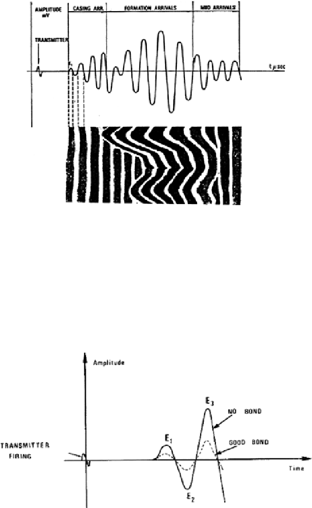
borehole fl uid. Thus, at the receiver, the signal recorded will have three major com-
ponents, the casing signal, the formation signal (if present), and the borehole signal.
The initial transmitted pulse will be spread out into a wave train. Figure
12.7
illus-
trates a typical wave train seen at the receiver.
Fig. 12.7
CBL wave train. Courtesy Schlumberger
Amplitude Measurement
Since the amplitude of the casing wave is required for the attenuation measurement
it is suffi cient to measure the amplitude of the fi rst arrival since this will be the one
that has traveled through the casing. For convenience, the various arrival peaks are
named
E
1
,
E
2
,
E
3
, etc.—
E
1
being the fi rst arrival. The form of the transmitted wave
and the fi rst arrivals at the 3-ft receiver are shown in Fig.
12.8
.
Fig. 12.8
Schematic receiver output signal with bonded and unbonded casing. Courtesy
Schlumberger
Search WWH ::

Custom Search