Environmental Engineering Reference
In-Depth Information
GRADIOMANOMETER
gm / cc
q
t
B/D
0
1
2
q
t
= 850 B/D
q
o
= 485 BOPD
q
w
= 365 BWPD
r
w
= 1.05
r
o
= 0.80
#1
850
5.5
Div.
7.5
Div.
#2
330
AMPLIFIED
GRADIOMANOMETER
10.5
Div.
#3
65
0
#4
17.0
Div.
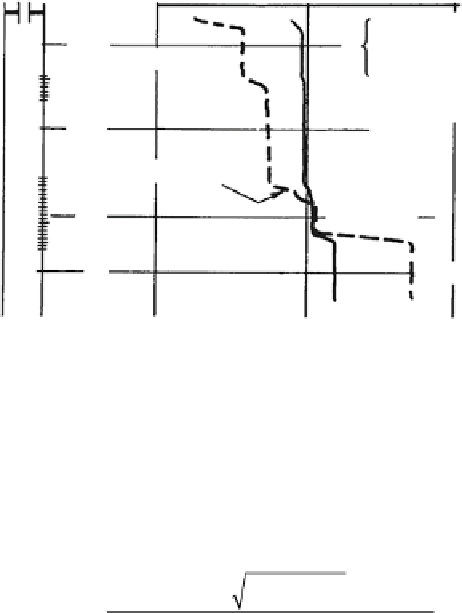
Fig. 10.3
Gradiomanometer log in a well producing oil and water. Reprinted by permission of the
SPE from Curtis (1967)
In order to rescale the gradiomanometer, two points on the log need to be consid-
ered. At Station #4, an assumption is made that the reading of 17.0 divisions cor-
responds to 100 % water, for which, obviously,
y
h
= 1.0. At Station #1, the reading
of 5.5 divisions corresponds to some value of
y
h
that can be back-calculated from
the known flow rates, casing and tool sizes, and slip velocity. Mathematically,
(
)
±
(
)
+
2
--
Q V QAV
-
4
QAV
t
s
t
s
h
s
y
=
h
2
AV
s
In this case, the product
AV
s
in B/D is computed as:
(
)
´´
2
2
p 49516875
4
.
-
.
AV
s
=
20 1 781
.
=
605 81
.
BD
/
The heavy-phase holdup at Station #1 is then calculated as:
y
h
=
-
244 19 971 65
2 605 81
.
±
.
=
06
.
´
.
An alternative method of finding
y
h
above all the perforated intervals is to use the
holdup and flow rate chart, as shown in Fig.
10.4
. By plotting the point correspond-
ing to 485 BOPD and 365 BWPD the holdup of 0.6 is directly determined.
The gradiomanometer may now be recalibrated in terms of
y
h
using the two cali-
bration points determined, that is:
y
h
= 1.0 when gradio reads 17.0 divisions
y
h
= 0.6 when gradio reads 5.5 divisions


Search WWH ::

Custom Search