Environmental Engineering Reference
In-Depth Information
Photodiode
Laser
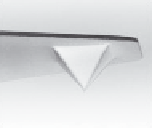
Cantilever tip
Piezo-electric
scanner
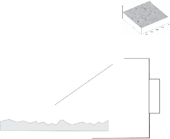
Figure 6.16
Schematic principle of atomic force microscope, showing the cantilever with
enlarged view of a cantilever tip, the laser balance with laser defl ection detection photodiode
and piezo-electric actuator scanner, and an example of obtained AFM force topography
image.
deviations in the cantilever oscillations and thus acts as a balance that can measure
both repulsive (Pauli principle) and attractive (van der Waals') forces in the range
from 10
− 7
to 10
− 12
N. These forces cause the cantilever to defl ect or change its
oscillating frequency if set to oscillate.
There are different ways of obtaining topographical imaging in AFM but they
are all based on coordinating the cantilever oscillation and the x- y -z scanning. In
contact mode, the cantilever tip comes in close contact with the sample and the
x- y -z scanner is set to scan over the sample in order to keep the tip defl ection
constant. The measured z-scanner positions are then used to make an image. It is
also possible to keep the scanning height constant and measure the defl ections as
a function of separating distance. The drawback of contact mode is that loosely
bound particles will be moved by the tip while it scans over them. Therefore, a
tapping mode (oscillating and briefl y touching the sample) and a non-contact mode
(where the tip is defl ected by the force interactions but not allowed to touch the
sample) are often selected instead. AFM can be used in air and in water. There is


Search WWH ::

Custom Search