Environmental Engineering Reference
In-Depth Information
Optical microscope
(transmission)
Electron microscope
(transmission)
Electron microscope
(scanning)
Light bulb
Electron guns
Cathode ray
tube (CRT)
High
Voltage
generator
Electron gun
Condenser lens
Signal
amplifier
Deflection coils
Specimen
Scan
generator
Objective lens
Fluorescent
screen of CRT
Final magn.
<100000X
Deetector
First image plane
Specimen
Projectior lens
Final image
Binoculars
or camera
Final magn.
<1000X
Fluorescent
screen or
camera
Final magn.
<1000000X
= Glass lens
= Electromagnetic lens
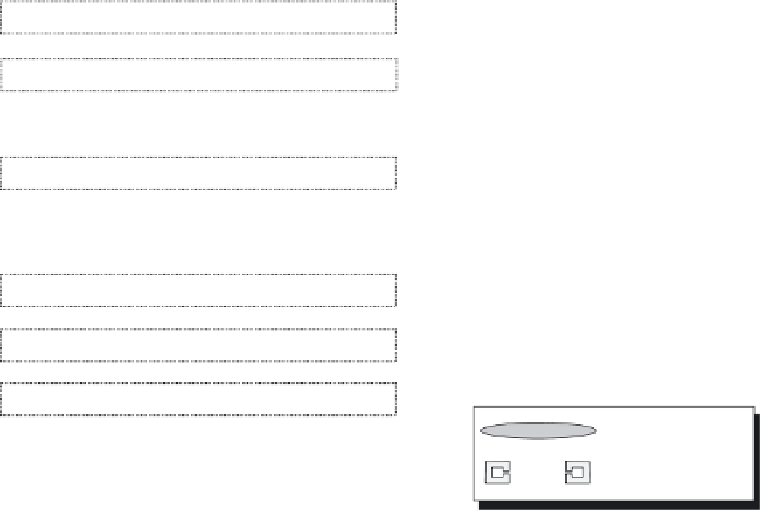
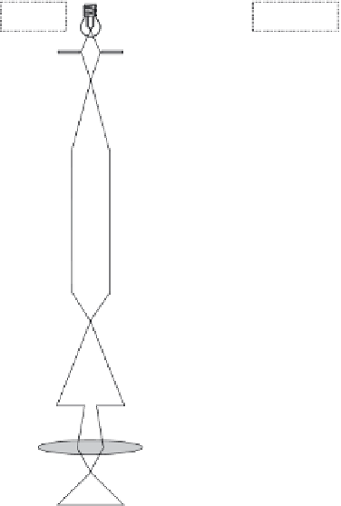
Figure 6.10
Schematic views of transmission and scanning electron microscopes and optical
microscope is shown for comparison. (Adapted from Wilkinson, K. J. and Lead, J. R. (2007),
Environmental Colloids and Particles: Behaviour, Structure and Characterization
, John Wiley
& Sons Ltd, Chichester.)
the aquatic environment, such particles will always be outnumbered by naturally
occurring nanosized materials. The challenge in the fi rst place will be to selectively
detect the engineered NPs. Thus, microscopic techniques that allow selective
probing of specifi c properties of the engineered NPs will be most promising.
Scanning electron microscopy.
In the SEM, a focused electron probe is scanned
over the surface of the sample and the detected signal is simultaneously projected
on a monitor. Different signals can be recorded in parallel (such as secondary
electrons (SE) and backscattered electrons (BSE)) providing different information
about the investigated sample. There is no direct path between the electron
beam and the image displayed and thus the signal can be electronically enhanced.
For SEM a large selection of excellent textbooks is available and a good intro-
duction into the topic can be found in Goldstein
et al.
, 2003. For a brief


Search WWH ::

Custom Search