Environmental Engineering Reference
In-Depth Information
A
B
C
polyvinylidene fluoride
polysulfone membrane
cellulose membrane
D
E
track-etched membrane
honeycombe AlOx 20 nm
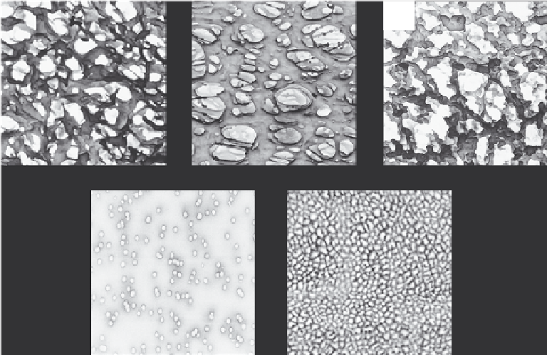
Figure 6.4
Detailed SEM pictures of different microparticle fi lter types. Upper row is showing
different depth fi lters with high porosity, while the lower row is showing sieve type fi lters
with well defi ned pore structure. (Images A-D reproduced with permission from Millipore
Corporation. Image E kindly provided by Frank von der Kammer (2005), Characterization
of Environmental Colloids applying Field-Flow Fractionation - Multi Detection Analysis with
Emphasis on Light Scattering Techniques, Hamburg University of Technology.)
Recirc.
pump
Recirc.
pump
CFF-membrane
CFF-membrane
Sample
Sample
Feed
pump
Feed
pump
Permeate
Permeate
Retentate
reservoir
Retentate
reservoir
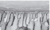
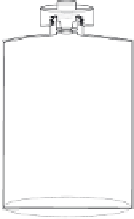
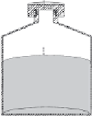
Figure 6.5
A typical cross-fl ow fi ltration setup with a sample vessel, a recirculating retentate
reservoir, pumps, ultrafi ltration membrane and permeate vessel. Inset microscopy picture
shows a surface of an ultrafi ltration membrane with larger supporting pore structure
underneath.


Search WWH ::

Custom Search