Environmental Engineering Reference
In-Depth Information
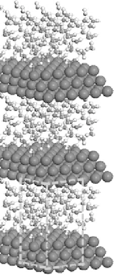
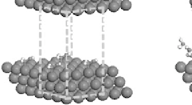
Figure 4.2 Graphical representation of the supercell structure, with a single (3
3) unit cell
indicated by dashed lines that is repeated along lattice vectors a, b, and c, as indicated. (a) and
(b) are vapor phase and aqueous phase models of the reaction environment, respectively, for an
adsorbed CH
2
OH intermediate with a surface coverage of
9
.
bottom layer of metal atoms are typically fixed at the experimental or DFT-optimized
values for the bulk fcc metal. The reader is referred to the original literature cited in
each example system for the specifics as to the generalized gradient approximation
exchange-correlation functionals, Brillouin zone sampling, plane-wave cutoff energy,
and pseudopotentials employed.
4.3.2 Aqueous Systems
The solution phase is modeled explicitly by the sequential addition of solution mol-
ecules in order to completely fill the vacuum region that separates repeated metal
slabs (Fig. 4.2a) up to the known density of the solution. The inclusion of explicit
solvent molecules allow us to directly follow the influence of specific intermolecular
interactions (e.g., hydrogen bonding in aqueous systems or electron polarization of
the metal surface) that influence the binding energies of different intermediates
and the reaction energies and activation barriers for specific elementary steps.


Search WWH ::

Custom Search