Information Technology Reference
In-Depth Information
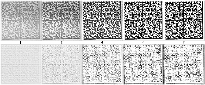
Fig. 8.12.
Recall of network trained for binarization of Data Matrix codes. The development
of the feature array activities at Layer 0 is shown for one of the degraded test examples.
(a) (b) (c)
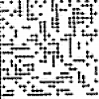
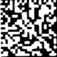
Fig. 8.13.
Recall of network trained for binarization of Data Matrix codes. Shown are ac-
tivities for parts of a degraded test image after 11 iterations: (a) original image; (b) hidden
feature array; (c) output feature array.
or horizontally, depending on the prominent local orientation of the corresponding
bright area. If such a local orientation cannot be determined, e.g. in bright areas that
have a larger width as well as a larger height, the blobs form a loosely connected
matrix.
Figure 8.13 zooms at the lower left corner of the code and displays the activities
after 11 iterations to illustrate this behavior. It is evident that the hidden feature array
represents discrete cells, covering about 4
×
4 pixels, rather than single pixels. The
blobs inhibit the output feature cells. Hence, network has learned that the output of
a cell must be coherent. This suppresses thin vertical lines and pixel noise.
To understand the emergence of the blobs, one can look at the contributions
made by input, lateral, and backward weights, as shown in Fig. 8.14. The weak
weights of the input projections detect contrast at the upper and right border of a
bright area. The contributions of lateral projections shape the blobs through a center-
center excitation and a center-surround inhibition. Here, the typical blob distance of
about four pixels is enforced. Finally, the backward projections excite or inhibit
entire areas, not discrete blobs. Thus, at Layer 1 a coarser representation of black
and white areas must exist.

Search WWH ::

Custom Search