Information Technology Reference
In-Depth Information
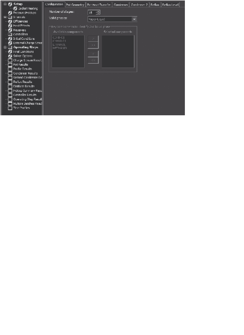
Figure 11.28
BatchSep basic setup.
An example of a batch distillation application is given at Examples/BatchSep
Example. Figure 11.27 shows a sketch of a batch distillation column. Stream 1 is
the batch charge, streams 2, 3, and 4 are the products (cuts), and stream 5 is the
pot contents at the conclusion of the distillation. Each of the product streams has an
associated receiver. BatchSep applications require Aspen Plus release 7.1 or higher.
The Setup form for the BatchSep block is shown in Figure 11.28. Note the possi-
bility of two liquid phases in equilibrium with a vapor phase. Each of the available
tabs enables definition of the physical dimensions of the still as well as the column's
overhead specification, such as the reflux ratio. The Jacket Heating tab enables the
choice and value of the bottoms specification. The tab Receivers permits definition
of the number of receivers and the association of each product stream with a par-
ticular receiver. The Side Draws tab permits the entry of all necessary side draw
information.
The Controllers folder facilitates the use of a simulated PID-type controller during
batch distillation. Figure 11.29 shows the two tabs that permit a user to choose a
variable to be controlled and the controller settings that operate the controller. This
capability enables one to simulate the real-time behavior of the batch still.
The input forms for the Initial Conditions tab are illustrated in Figure 11.30. Both
the Main and Initial Charge tabs are shown.
Control of the products of the distillation is done with the Operating Steps entry.
In this example there are two operating steps to the process. Figure 11.31 shows the
setup of Stepone. When all the steps have been executed, the Final Conditions entry
permits the choice of disposition of the contents of the reflux drum, the packing, and
the pot.