Graphics Programs Reference
In-Depth Information
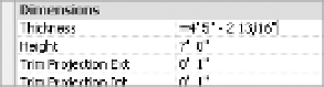
size is after you subtract a 3 5/8ʺ stud and 5/8ʺ piece of gypsum board from an 11ʹ-2ʺ room?
Don't. If you need to modify a dimension, simply add an equal sign and a formula
(Figure B.17), and Revit will calculate the value for you.
F igu r e B .17
use an equal sign for performing
calculations.
Make elevators visible in your plans.
Y
ou want to create a shaft that will penetrate all the
floors of your building and put an elevator in it that will show in all your plans. You could
do that with an elevator family and cut a series of holes in the floors by editing floor profiles,
but sometimes those holes lose their alignment. Fortunately, you can do both things at once
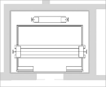
using the Shaft tool found on the Opening panel of the Architecture tab. Here, not only can
you cut a vertical hole through multiple floors as a single object, but you can also insert 2D
linework to represent your elevator in plan (Figure B.18). Every time the shaft is cut in a plan
view, you will see the elevator linework.
Figure B.18
adding an elevator to
a shaft
Orient to view.
Creating perspective views of isolated design elements can be quick and
easy in a plan or section, but let's say you want to see that same element in 3D to be able to
work out the details. Here's how:
1.
Create a plan region or section cut isolating the area in question. If you're using a sec-
tion, be sure to set your view depth to something practical.
2.
Open the Default 3D view or any axon of the project.
3.
Right-click the ViewCube
®
, select Orient To View, and select your view from the context
menu.
4.
Now, your 3D view will look identical to your section or plan region, but by rotating the
view, you'll be able to see that portion in 3D.