Graphics Programs Reference
In-Depth Information
In addition to simple gaps, parts can be divided with a custom profile. A family template
called Division Profile.rft (Metric Division Profile.rft) is now available in the
default family template library. This profile family is similar to other profiles except that the
completed sketch in the family does not need to be a closed loop. That said, the sketch must
extend completely between the two reference planes associated with the Width parameter in the
template.
A number of division profiles are loaded in the default architectural project template. You
can find these in the Project Browser under Families
➢
Division Profiles. To examine how any of
these are created, right-click Tapered Notch and select Edit from the context menu.
Let's explore how you can edit an existing division and apply a custom profile to the gap.
Follow these steps:
1.
Continue to work with the project file c19-Parts-Start.rvt or c19-Parts-Metric-
Start.rvt from the previous exercise. Activate the Parts Model 3D view, and orbit the
model to view the exterior face of the wall.
2.
Select any one of the divided parts of the main precast concrete portion of the wall. Once
a part has been divided, you won't need to select all the parts to edit the division, just
one. From the contextual ribbon, click Edit Division.
3.
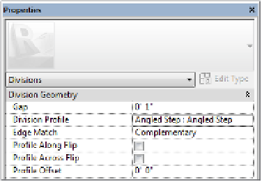
In the Properties palette, change the Division Profile parameter to Angled Step: Angled
Step. Once you select a profile type, additional parameters are available in the Properties
palette. Set the Edge Match parameter to Complementary (Figure 19.23).
Figure 19.23
assigning a divi-
sion profile to a
part
4.
Click the green check mark in the ribbon to finish the division edits, and you will see that
the updated profiles are applied to all edges of the divided parts (Figure 19.24).
Figure 19.24
Parts divided with
a division profile