Graphics Programs Reference
In-Depth Information
The Legend tool is located on the Create panel in the View tab. There are two types of
legends you can create from this menu: a
legend
, which is a graphic display, or a
keynote legend
,
which is a text-based schedule. Both legend types can be placed on multiple sheets, but for this
exercise, you'll focus on the graphic legend. The keynote legend will be handled in more detail
in Chapter 18, “Annotating Your Design.”
As part of the sample workflow, you may want to present some of the wall types as part of
your presentation package to demonstrate the Sound Transmission Class (STC) of the walls and
the overall wall assembly. Because these wall types will be appearing on all the sheets where
you are using them in plan, you'll make them using a legend.
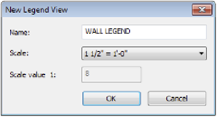
To make a legend, choose the Legend button from the View tab under the Legends fly-out.
Creating a new legend is much like creating a new drafting view. You'll be presented with a
New Legend View dialog box (Figure 17.24), where you can name the legend and set the scale.
For this legend, name it
WALL LEGEND
and choose 1 1/2ʺ = 1ʹ-0ʺ (1:10) for the scale.
F igu r e 17.24
creating a legend
The legend you've created will look like a blank view. At this point, it's up to you to add
content. The simplest type of legend would be adding notes such as plan or demolition notes
that would appear in each of your floor plans. You could do this simply by using the Text tool
and adding text within this legend view; however, in this example you want to add more than
just text.
To add wall types or any other family to the legend view, expand the Families tree in the
Project Browser and navigate to the Wall family. Expand this node and then expand the Basic
Wall node. Select the Interior - 4 7/8ʺ (138 mm) Partition (1-Hr) wall type, drag it into the view,
and insert it anywhere.
With the family inserted into the view, it will appear as a 3ʹ (1,000 mm)-long plan wall.
Change your view's detail level from Coarse to Medium or Fine so you can see the detail within
the wall. With that done, select the inserted wall and look at the settings in the Options bar.
These options will be consistent for any of the family types you insert. The Options bar for
legend elements consists of three sections:
Family
This drop-down menu allows you to select different family types and operates just
like the Type Selector does for other elements within the model.
View
The View option lets you change the type of view from Floor Plan to Section.
Host Length
This option changes the overall length (or in the case of sections, height) of the
element selected.