Graphics Programs Reference
In-Depth Information
project for clarity
. The software has attempted to calculate your plan area based on some
predefined rules. For the most part, it does a reasonable job of figuring out where the
boundaries are, but from time to time those lines need some adjusting. You will learn
over time whether this automation works based on the complexity of the perimeter walls
in your designs. If they are complex and not clearly closed, the results of the automated
boundary placement may be undesirable.
In the Project Browser, find the node Area Plans (Gross Building) and open either of the
plans. Notice the difference in the application of the area boundaries to the exterior walls.
The area boundaries are applied to the outside faces of the exterior walls. In the Usable
Area plans (Figure 17.6), the boundaries are assigned to the inside faces of the exterior
walls—also adapting to window elements.
To complete this part of the exercise, you will place additional area boundaries to subdi-
vide the interior space into different spaces.
6.
Activate the Level 1 area plan for Usable Area. From the Architecture tab, select the Room
& Area panel; click Area Boundary.
The default drawing method is set to Pick, and in the Options bar, the Apply Area Rules
setting is checked. Remember that this setting determines whether the location of the
boundary will be affected by the Area Type property of the areas placed on either side of
t h e b ou nd a r y.
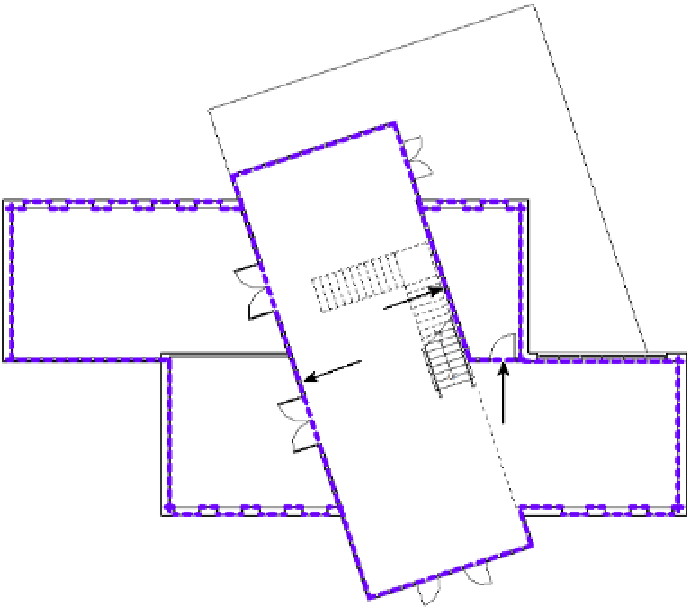
7.
Pick the interior walls indicated in Figure 17.7.
F igu r e 17.7
Place additional area
boundaries on level 1
as shown here.